Saturday, December 1, 2012

RC Receiver Data Transmission

It's getting cold outside, so connecting the real RC transmitter to a flying simulator would be awesome!

Actually, it is so awesome, there are a number of projects like that already on the internet. Like RCArduino (reading RC controller with an Arduino), or PPM RC to USB (reading RC controller's PPM signal).

But here, something different is required, something that reads the RC receivers signal to the servo, converts it to an 8bit value, and sends it over the USB port. That way, any receiver could be connected and any channel read.

So, step one, check how the signal of a RC receiver looks like:


It looks like a standard servo PWM signal (1ms for far left, 1.5ms for center and 2ms for far right), with no delay between switching from one channel to the next.

Sunday, November 11, 2012

Upgrading the Camera Stand Again

Fixed the right camera hanging to the side by cutting and bending the holding plate with the screw. Just 2.5° difference, but it makes all the difference. Still slightly rotated, but around the center, which is less of a distortion.

(Do not look at the picture without 3D glasses!)


But why stop there. Since this will be on a plane someday, let's fixate the camera so it wont rotate around the mounting screw.


And for convenience, a small cut out to the holding plate, so that the camera latch can open and expose the battery and memory card (screwing and unscrewing the camera to the stand over and over again becomes old really fast).


Saturday, November 3, 2012

Rolling


Finally, standing on wheels!

Trimmed away decorative plastic from the landing gear. Saved about 35 grams.

Sunday, October 21, 2012

360° Panorama Coordinate Systems

Unwrapped pictures from the 360° panorama lens, treated with b-splines, looked pretty. But they weren't right.

How do we know? We checked:


And for that a 360° panoramic calibration checker board was created.


Confused yet? Pay attention to the height of the squares. Still confused?


Unwrapping the picture with Polar to Cartesian transformation, we can see that the squares aren't square. In fact they get less and less square.


It turns out that the correct transformation would be from Log-Polar to Cartesian coordinate system. And even then with a calibration parameter for the lens, since the real world is not perfect and the log base != e.


So we get, what the camera sees.


What we want to see.


What math sees.

Tuesday, September 11, 2012

Data Set Test Again

New stand, new data, new problems.


While working with the stand is much easier now, it would appear that the red camera holder is glued with together with a slight tilt to the right.


Back to the "shop".

Sunday, September 2, 2012

Upgrading the Camera Stand

Small problem with the original idea.

Sure it works, but using metal screws for the cameras and metal clamps to attach them to the stand, left the whole thing heavy. Too heavy for the specifications of the plane.

Time to innovate! Easiest and lightest thing would be to attach another pair of bigger tubes over existing ones, using them as tracks to hold the cameras while still being able to adjust them.

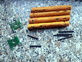
Fresh out of those, we make our own:


Wrap some shrink wrap around the tubes, to use them as a mold:


Wrap some strong fabric around the mold. In this case, polyester canvas fabric. And drench it in super glue.


Let it dry and then pull off the mold carefully.


Sand off imperfections until smooth.


Cut to equal lengths, drill holes for camera holder and spaces. Reuse parts from previous version, but cut away anything unnecessary to keep the weight down.


Again wrap the stand in shrink wrap, put on all the parts and drench it in super glue again.


Replace the metal screw with a plastic one.


And we're done!

In previous version, a single camera holder was 73 grams, this version is 14 grams. Altogether a reduction in weight by 118 grams (118 = 2*73 - 2*14).

Sunday, August 12, 2012

Meteors and the Moon

Moon rising on the night of Perseid meter shower.


Meteors

Perseid meteor shower captured with the Canon's A2200 camera using CHDK to override the exposure to 20 seconds and a script to continuously take pictures till the battery runs out.

But even with ISO set to 1600, the majority of the meteors were to short lived and not bright enough to be captured.


Monday, August 6, 2012

Science & Engineering

Curiosity successfully landed on Mars!

To celebrate here's a 10x enlarged photo of the descent using b-splines.


Sunday, August 5, 2012

B-splines "HD"

Full resolution panoramas with nearest pixel values and sub pixel values.


B-splines

What an interesting thing this is.

With it you can resize this:


To this:


Without looking like this:


While used to describe continuous surfaces in 3D models, their ability to produce a value at sub pixel resolutions con be abused here to unfold the 360° panorama more smoothly.

Panorama when unfolding with the nearest pixel to the calculated value:


Panorama when unfolding with the sub pixel value:


The down side is that using brute force to calculate every pixel amounts to couple of hours per full resolution image.

Next step, use science & math to speed things up!

And to finally fix the aspect ration (now that the images are smooth).

Wednesday, July 18, 2012

Data Set Test

Time to collect some sample data!


The plan was, take a stereo picture with the lenses apart from 155 mm to 955 mm with 50 mm intervals. After that, process them and see how the space between lenses correlates between produces images. That was the plan.


What I did discover is that there is a small design flaw in the set up. The mount that holds the camera is prone to swivel when moving the camera left or right on the tubes. Which means that if not really careful, the cameras weren't always pointing perpendicular to their location. Which means the depth perception doesn't correlate with the camera position.

But the pictures are awesome!


Thursday, June 28, 2012

It's all About the Ratio


That's better!

Sorting out the aspect ration issue (should the width and height be determined by the difference of surfaces from inner our outer circle or be set by the radius & circumference), still needs some work.

But the next big challenge is to antialise the image.

Tuesday, June 26, 2012

1 != 1

And suddenly the problem comes in to focus!

It was not, as previously thought, a problem with the lens distortion or pixel shape. Or any other mythical unexplained reason. No, just a simple mix up with with the normalisation of the vectors.

If the image is not equal in height and width, then 1 X != 1 Y.


Monday, June 25, 2012

3D Glasses Needed

With the stand built, remote trigger working and synchronisation tested, it's time to take some 3D pictures!

Left eye - Righty eye


"Third" eye :P


The process works. Time for actual science!

With the lenses 24cm apart it's a bit to much perspective for humans (at least for the object in the front). But for a computer, who knows.

Camera Synchronisation

And now, the whole adventure that was porting the CHDK comes to this, taking synchronised images from multiple cameras at once. But it's still not that simple!

First we need some more hardware that will trigger the cameras:


Build after schematics on CHDK wiki, the voltage trigger works.

But now it needs to be tested with two cameras, to see if the image acquisition is synchronised, so we need one more piece of hardware:


A true scrap heap project composed of an unused electric motor from a model plane, some spare electronic elements, a CD holder from an ancient MacBook's CD drive and a brand new DVD which was drilled trough so a LED and a battery was mounted on it.

With this the synchronisation wheel came to be. By using the known exposure values on the camera and tracing the light trail made by the LED, the rotational speed was calculated to about 10.36Hz.

Now with this information the synchronisation between the cameras can be calculated:


Taking the same picture with both cameras at the same time with the trigger, the angles from the start and en of the light trail can be measured and compared.

So far, the exposure time was the same and worst calculated delay between the cameras was 0.3ms. Not bad, but this may still vary a bit, since so far it has only been tested with few pictures and on one set of settings.