Wednesday, December 4, 2013

Testing Structure From Motion Software II

Let's try to get some real data with some real pictures.

On the last flight, lasting 5 minutes 33 seconds a total of 134 pictures were taken (67 with each camera).

Out of those, 38 were matched to a single scene in VisualSFM:


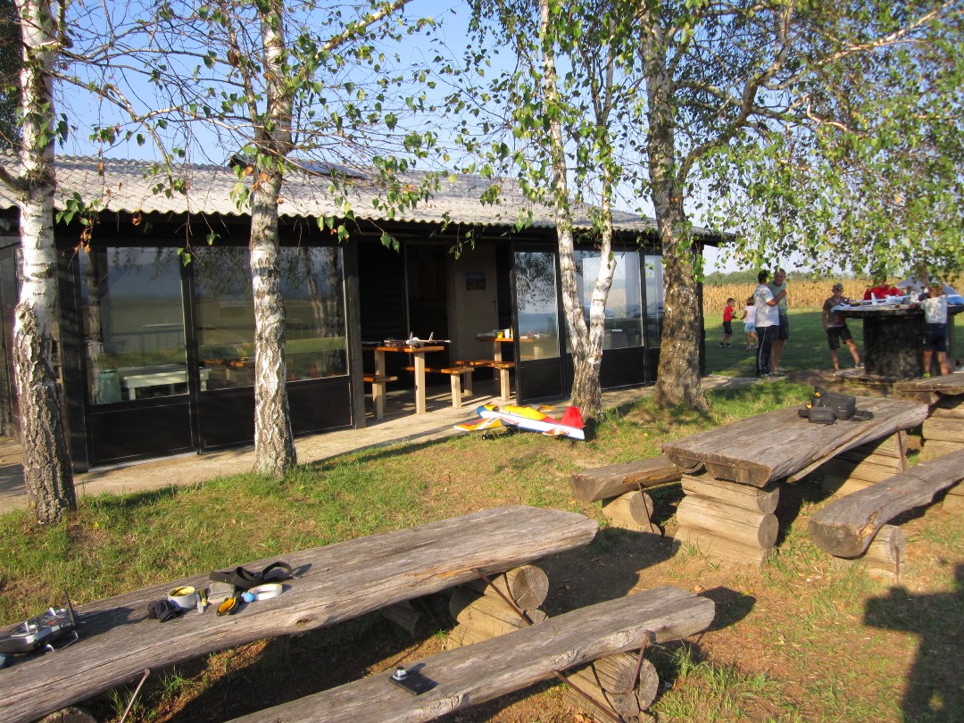
This time the results are much more better. The shape of the house or the vehicles parked outside can be easily distinguished.

And when combined with CMPMVS:


Also showing produced disparity map and generated ortophoto picture of the scene:


The results look good! Houses, roads, bushes, trees and even separate fields can be distinguished now.

But they could be better still. For one, while focus was locked, the exposure and ISO weren't and the cameras "decided" to take pictures at shutter speed 1/100 s with ISO 80. Manually decreasing the shutter speed and increasing ISO would produce even sharper images.

Secondly, decreasing the time between shots would mean more images and more overlapping matching points. Now the shots were taken at 5 second intervals. This could be reduced to 4 seconds for stereo images.

It could be even reduced down to 2 seconds between pictures if the cameras would take turn taking pictures, but then this would become purely structure from motion reconstruction (as it was here if we can't get the stereo registration to work properly).

Monday, December 2, 2013

Seventh Time in the Air

In in the air again to take some pictures.

The plan was simple. Utilize the battery (3 minutes full throttle or 9 minutes half throttle) to the fullest.

Start with 1 minute of full throttle to get some altitude, 66% or 6 minutes half throttle left. Flay a couple of overpasses for 4 minutes, 2 minutes left at half throttle. Land with remaining battery.

Sadly the plan didn't go quite as planned:


First take off attempt was aborted because one of the wheels snagged on the grass and turned off the runway (here were 10 seconds of full throttle lost). Then the plane didn't get as high as intended, so flying by the visible size, the plane was flown farther then intended (here it took longer to fly back). Add some wind higher up, so when trying to hold the plane as still as possible for the photos produced larger turns.

Long story short, 5 minutes and 33 seconds later the plane landed 3 meters from the runway because it ran out of power to run the motor 20 centimetres off the ground approaching the runway. But the new landing gear held. No pivot over this time, just some torn duct tape.

Much was learned today and if the pictures turn out useful, it was worth it.

And here is the scenic view:


AVI@TOR MK4 SP5

We need pictures! And for that the plane needs an upgrade.

First of, a better landing gear:


Made from a spare PCB board from another project as a base (strong and flexible). To which a set of foam and plastic wheels on flat carbon bracket were mounted.


Attached with duct tape, the landing gear work perfectly. The PCB base bends under load and if there is any excessive force applied it goes to the duct tape which breaks and tears but is easy replaceable.


Only the bent rod holding the wheels to the carbon bracket kept braking from the glue. Quick fix, reinforced with zip-ties instead of just glue for extra strength.

Now the plane is finally ready for the extra weight of the camera mount, without the need to fix the landing gear after every heavy landing.

And second, to take pictures we need to synchronise the cameras! Yes, the board to let the phone control the servos and the cameras (to synchronize GPS data with shots taken) is in the works, but for a quick test lets use what we have:


Just change the firmware from our rc2usb board to output a second long pulse every 5 seconds instead of the PWM for the servo tester.


Now cut up and strip down a couple of cheep mini USB cables to get the connectors, wire up the power lines to the pulse output on the board and run the wires trough the camera stand.


We are now ready to take some high resolution pictures!

Thursday, November 28, 2013

Testing Structure From Motion Software

So, while we work on improving our implementation of image rectification and beyond, let's see what kind of results we can expect from the data we have.

For that, we're going to use a couple of freely available reconstruction tools that already work.

First one is VisualSFV: http://ccwu.me/vsfm/

A GUI application for 3D reconstruction using structure from motion (SFM) from Changchang Wu.

For that we took our stereo video from the last time. Extracted images from the left camera at 5 images per second (extracting images from both cameras was just too many images, and we still don't have them rectified). Used OpenCV and a calibration board to fix the lens distortion and ran it trough VisualSFM.

The result being sparse and dense reconstruction:


And the output in MeshLab:


Once we had the dense reconstruction, we were able to export it from VisualSFM in .cmp format, which can be used as input for the next tool.

Second one is CMPMVS: http://ptak.felk.cvut.cz/sfmservice/websfm.pl?menu=cmpmvs

A multi-view reconstruction software.

So after letting it do all the work, we ended up with the model:


The results are promising, but there  is a lot of noise in the reconstruction. Looked closely there are differences in disparity where there are houses, but just. The details like cars are lost.

Looking at single video frames, the images still look slightly blurry. Even though the plane vibrates a lot less now, maybe taking images for reconstruction as video is not the best method.

Time to take some real photos and try with that.

Monday, November 11, 2013

Playing with Disparity

Pictures and videos from the plane look cool, but that's all if until we do something with them. And what do we want to do with them? We want 3D reconstruction!

Sounds scary. It is. It takes a lot of math to do 3D reconstruction with epipolar geometry, so we're going to start slow and first play around with disparity map from stereo images.

Nothing extravagant for now, everything done here with python, opencv for python and numpy.

Step 1: take two cameras, take a stereo image pair and take a picture of a checkerboard with each one for calibration.


Step 2: detect the edges (hint: cv2.findChessboardCorners).


Step 3: calibrate the camera and fix the distortion caused by the lens (hint: cv2.calibrateCamera, cv2.getOptimalNewCameraMatrix, cv2.initUndistortRectifyMap).


Step 4: find detectable features on both images, here we're going to use SIFT algorithm  (hint: cv2.SIFT()).


Step 5: find the same matching features in both images, here we're going to use the FLANN algorithm (hint: cv2.FlannBasedMatcher, cv2.FlannBasedMatcher.knnMatch).


Step 6: compute epipolar lines between pictures (hint: cv2.findFundamentalMat, cv2.computeCorrespondEpilines).


Step 7: transform the images so the matching lines will be horizontal with each other between images (hint: cv2.stereoRectifyUncalibrated, cv2.warpPerspective).


Step 8: calculate disparity between two stereo images (hint: cv2.StereoSGBM, cv2.StereoSGBM.compute).


So much for the first try. The disparity map is noisy and not really accurate on the account of uncalibrated stereo rectification.

To improve that we need to perform calibrated stereo rectification, and we'll be able to do that when we figure out the way to get rotation and translation data between stereo sets from epipolar geometry.

Also, a great resource of learning opencv and python: https://github.com/abidrahmank/OpenCV2-Python-Tutorials

Monday, October 14, 2013

Sixth Time in the Air

Fully assembled once more, it's testing time!


With only the control circuit between the autopilot program on the phone and the plane for autonomous flights missing, the weight of the plane is now just below 1.9 Kg. Not bad for all the equipment.

But is it better? Yes!

First, the vibrations are almost gone:


Left picture, previous flight, fully loaded with the stock motor at full throttle.
Right picture, this flight, fully loaded with the new motor at full throttle.

The difference is enormous:


And that's not al. With the new engine, the plane now climbs effortlessly:


In this test, with no one around on the ground or in the air, altitude difference of around 300 m was achieved.

And with no problems with telemetry this time, we learned that the cruising speed at which the altitude can be maintained is around 45 Km/h, which takes about half throttle.

Unfortunately, but not unexpectedly due to all the extra equipment, the gliding profile is somewhat disappointing. With the engine off, the plane glides, but the vertical speed necessary to maintain the cruising speed is around -35 Km/h, peeking at -50 Km/h. In short, it flies but it eats up altitude like crazy as can be seen on the video above at 3:00 mark (yes, the propeller keeps spinning due to resistance).

But, smoother and more powerful motor means better images and video from the cameras, and that's what we want!

Warning, awesome stereo video of the flight: