Saturday, August 31, 2013

Fifth Time in the Air

Fully loaded and air worthy:


Any yes, it flew! Here's the video to prove it:


And that's not all it did. The camera system works! It successfully takes pictures and video:


Stereo pictures! Might be uncomfortable to look at since the lens distance is not optimized for human viewing, but the depth data is there.

Still taken, synchronized and aligned by hand. There is one more part missing from the plane, and that is the circuit that will relay the data from the autopilot running on the phone to the servos. And part of that will also be automatic synchronised picture taking. As for the alignment, that will be the fun part once we have some real data.


And yes, there is also stereo video. Slightly easier for humans to watch, since distance between lenses is offset by the distance to the object in focus.

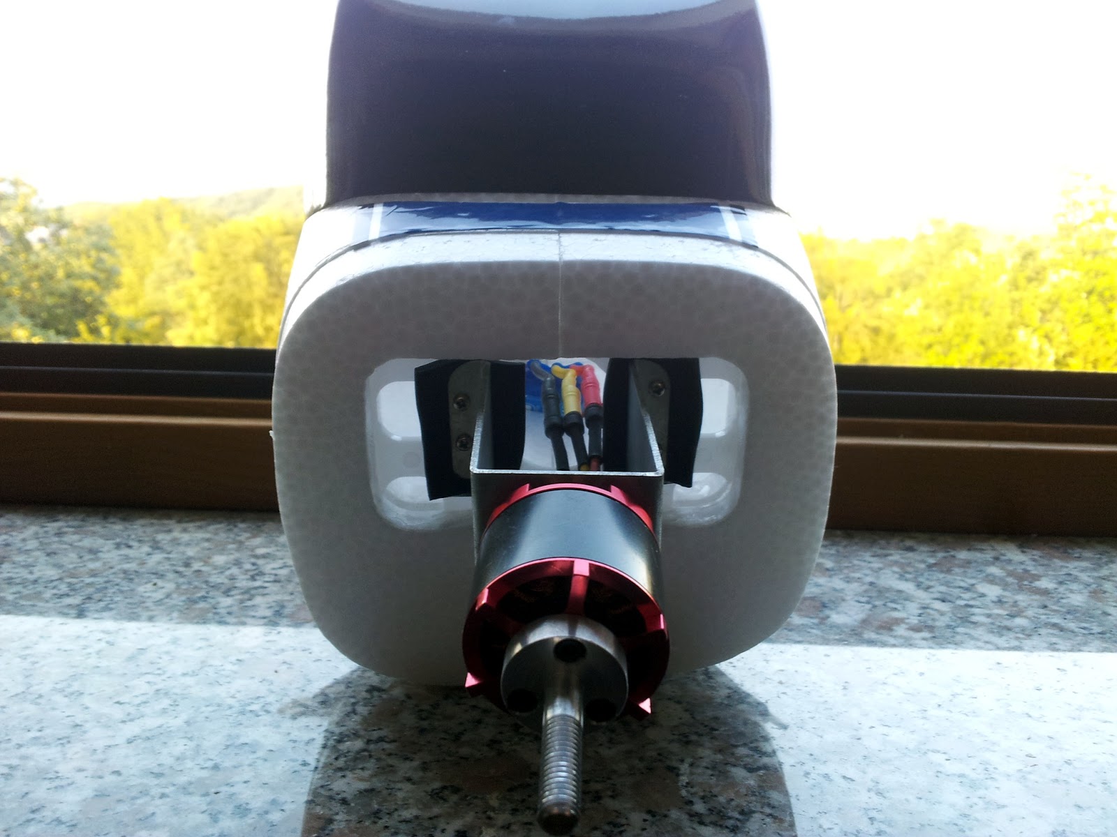
But unfortunately the video taken is slightly blurry.  Fault of the stock engine, which is not of the best quality and is causing much vibrations, which are also noticeable on the panoramic video. Not much can be done here but to replace the engine with something better.

And while we're at it, replace it with something more powerful, since while the plane flew, and it flew quite stable, it had horrible climb rate and required full throttle to maintain altitude.

Now with three cameras on board, there is one more flight video:


The landing could be better :P Not used to the extra weight, the runway was missed by 30cm, touching down on high grass and flipping over. So nothing but pride was broken.

And what would a report be without the visualization of the whole flight:


Unfortunately there was problem with the SD card in the phone, so not all the data was captured hence the lack of attitude visualization and force graphs.

All in all a very successful test flight. What works and what doesn't is known, so the next logical step is to work out the kinks and try again!

AVI@TOR MK4 SP3

We know the plane flies and can even do some simple acrobatics. But the real question is, can it fly with all the equipment?

Only one way to find out, which means it's time for some more modifications!

First we determine the location of the camera mount on/in the fuselage:


Keep in mind where the center of gravity will be once the cameras are on the plane, then cut the carbon tubing holder size box on one side and appropriate placed holes on the other side of the plane.

Center it just right and it looks like this:


Now that we have the camera holder in place it's time to use the camera holder mounts we prepared and printed.

The mounts will hold the holder to the wing so it wont move about and also to redistribute the weight a bit more evenly:


First locate and mark a good spot, close enough that will hold the stand and leave enough room so the cameras could be put on, but still far enough so the stand can be slide in and out.

Then mark the spot, carve it out (watch out for the servo wires) and protect the servo wires with wax (so once everything is coved with glue and the plane is beyond repair we can remove the servos without it's wires being glued).

Once that is done, drill appropriate holes in to the mounts so the fit around the carbon tube holding the wing, fit them inside the holes and drown them in glue.

After some time when the glue is set, we have out wings with mounts that look like this:


To fully assemble and disassemble the plane now is a whole process, but it's worth it when the end result looks like this:


Will it fly? Only one way to find out :P

Tuesday, August 27, 2013

From Imaginary to Real World for Real

Knowing the full process, it's time do make the part that will hold the camera stand for real.

First we need some quick measurements,so we can call it engineering instead of art:


Then some modelling:


Then proofing and fixing the model:


And finally, setting up and printing:


Two parts, two slicing methods, to see which one works better. First one without support beams and the second one with. The hollowed out back part held better shape with support beams (not being squished by gravity), but other then that, was about the same.

And of course, the final product:


Support beams removed and rough edges sanded. Now we're ready for the next plane upgrade!

Sunday, August 25, 2013

From Imaginary to Real World

So, the plane flies. Now we need to put the 3D camera stand on it!

But the stand has quite a bit of weight to it, not to mention it's not exactly a "plug and play" part for the plane.  Solution?

Make a holder for the stand for the camera :P And the easiest was to do it? Print it :D

So it's another skill we're learning here. And to learn it, let's make a simple spacer for the rods, to test the process and the scale of the printed product.

The process is "simple" ...

Step 1: design the part. In our case, we're going to use Blender.


It's free, it's powerful and (after checking some tutorials) the newer version has a 3D printing toolbox which saves some trouble. But in out case, we just used a measurement plugin to to check the distances. Once you're done, change Blender Units to Metric Units and export as .STL file.

Step 2: check the part for errors. In our case, we're going to use netfabb.


Very powerful and expensive software for 3D printer modelling and prepping, but the free version let's you do some simple editing and error checking. We fix any holes in the part, set the correct scale (turns out Blender to Metric conversion is 1 Blender Unit to 1 m not 1 mm) and export the now checked and ready .STL file.

Step 3: slice the file so the printer can print it. In our case we're going to use Slic3r.

No screenshot here, but you're not missing much, just the settings for your printer. Hope everything is calibrated and now you can get your .gcode file for the printer.

Step 4: print it. In our case we're going to use RepRapPro Mandel 3D printer and Pronterface program.


Nothing to do here, but wait and see what comes out.

And once it's done printing and you let your parts cool down, you get something like this:


Not bad for the first try. Some quick measurements and we have almost exactly what we wanted. Turns out that he melted plastic and the resolution of the printer "blurred" the part ever so slightly.

The hole was supposed to be exactly 10mm, but it came out 9.5mm. Which means the plastic in our case expands 0.25mm outside the designed boundary, which is not bad at all.

Step 5: optionally (but in our case mandatory) process the part with some sand paper or a drill.

Slightly smoothing and enlarging the hole and we have a perfect fit:


And now that we know how, let's start on the real thing! What is "the real thing"? join us next time and see for your self.

Sunday, August 11, 2013

Fourth Time in the Air

Some more flying experience, this time in the wind.

And just so, it won't always be the same, this time the panorama render was shifter for 90° (left side is the view to the front and right side is the view to the back):


And visualization of course:


And what would be a training session without bloopers? Not so educational. :P

Turns out, that you can do loops and rolls with this plane on purpose too, but you better have everything mounted on with enough strength to withstand the extra forces!

Or on your next flight, right after levelling from a loop, the battery decide to fly away in a different direction. But luckily, with no control, the plane managed to find the only bush near and far and landed "softly":


Couple drops of glue is a bargain for telemetry data:


Next up, more duct tape and more practice.

Sunday, August 4, 2013

Third Time in the Air

The last batch of modifications helped!

Placing the battery further behind stopped the plane from being nose heavy and improved stability quite a lot.

Well, the first try was maybe a bit too tail heavy for a change:


So after a quick couple of laps the plane was (perfectly) landed, battery readjusted and put in the air again:


Around 9 minutes of flight time (2 minutes first round and 7 minutes second round) with a total of 7.3 Km of distance travelled all together.

And now: practice, practice, practice, collect some sensor readings for the autopilot and practice. Before the stereo camera mount gets mounted! :P

Saturday, August 3, 2013

AVI@TOR MK4 SP2

More experiences brings more knowledge, and more knowledge brings more improvements.

Second service pack for the plane!

First to fix the nose heavy problem, the battery bay was extended towards the tail:


First, cut out and extend the battery bay. But look, now we can see inside the plane. Well, that's bad. No where to stick the battery to.


So we make a plastic holder from cut out plastic strips from various plastic packages.


And after some glueing and trimming we have an extended battery bay, which allows for better weight distribution by placing battery farther back from the center of gravity.

And while we were at it, let's put some silicon pads between the engine and the mount, just to see if it will reduce some vibrations.


But not before firmly glueing the plastic engine mount to the fuselage. It might have been damaged by a previous rough landing or it wasn't glued on well from the start, but it swivel up and down a bit when some force was applied to it.

Time for some more testing!