Well, the platform works. The plane flies, the phone steers it, camera takes pictures and software process it. Now, let's tie it all together, and while we're at it, let's upgrade some parts too.
Current limitations to overcome: increase flight time (larger batteries), eliminate the need for a runway and easier transport and assembly. The answer, a bigger and better plane.
Introducing Avi@tor MK5, a Hobbyking EPP-FPV frame with some custom modifications. A pusher plane with the engine on the back that doesn't need landing gear to raise the propeller from the ground, which means it can land anywhere. With a wingspan of 1.8 m it can carry a larger payload, in our case more batteries. To improve it we raised the horizontal stabilizer for easier landings in tall grass. We also improved the strength of the frame by covering it with sturdy canvas soaked in cyanoacrylate glue (poor mans carbon fiber) to better withstand increased weight and rough landings. And designed a wing holding and attaching piece also out of canvas soaked in cyanoacrylate glue to replace stock mounting with rubber bands for increased durability.
The build:
What came in the box (with some tools for the operation prepared in the background). First thing to do, reinforce the horizontal stabilizer with a spare carbon fiber rod.
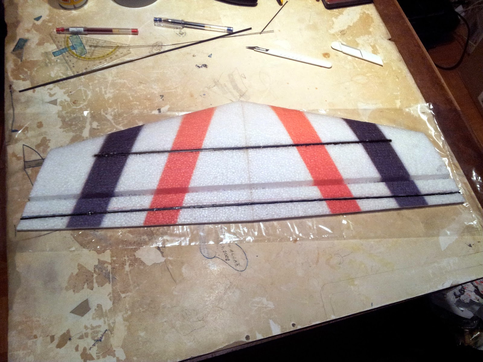
Next alight the wings, wrap them in clear film, cut a piece of canvas to size, align again and start soaking in glue.
Cut off and recess the the wooden support for the wing mount so it's flush with the fuselage (it'll make sense later).
Extend & expand the obviously too small vertical stabilizer and reinforce it with another spare carbon fiber rod trough the middle. Secure it to the horizontal stabilizer.
Fortify the bottom of the fuselage with the canvas soaked in cyanoacrylate glue combo.
Remove the canvas soaked cyanoacrylate glue mold from the wings, alight it with the fuselage and add more canvas against it. This will make for the reinforced wing assembly that could be easily assembled.
Cut out, align & glue some wooden support pieces that will hold the wing assembly together.
Drill and glue support carbon fiber beams in to the fuselage, also to help hold the wing assembly together.
Also drill the corresponding holes in to the wings and reinforce them with some more wood.
Fill the holes to size with cyanoacrylate glue, using clear film to wrap the carbon fiber beams as molds.
Once dried, cut and sand the beams to the exact size of the wings.
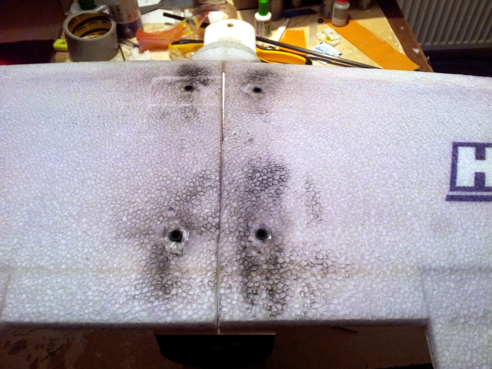
Fit everything once more just to be sure, then glue in the tail boom.
Extend the leads of some high quality servos, wrap them in duct tape (just in case they are ever to be reused in the distant future when the plane spontaneously catches fire), and glue them firmly into the horizontal stabilizer.
Run the wires across the height of the vertical stabilizer, add some some canvas strips and glue for protection and rigidness, and glue the tail section on to the tail boom.
Put a nut on a string and run it trough the tail boom and out the prepared hole in the fuselage. Then tie the servo leads to the string and pull them trough the boom in to the fuselage. Once installed, solder on a servo connectors.
To secure the servo leads and connectors, take a bottle cork, cut it in half, hollow it and glue the wires inside of it. Then just jam it in to the hole.
Once again fit everything, then cut the ailerons on the wings turning them in to ailerons and flaps.
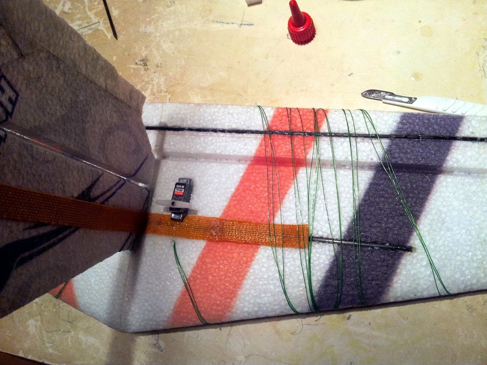
Extend some more leads of high torque servos (just in case) and glue them in to the wing.
To reinforce and lift the motor mount to create enough of a clearance for a bigger prop, cut out and glue a bigger wooden piece.
Then drill the holes in the appropriate places, color it and mount the motor.
Now just add the batteries, wire everything up, check for center of gravity and we're ready for the maiden flight.
Monday, March 31, 2014
Tuesday, February 25, 2014
The AutoPilot lives
Time to tackle this one!
This time with control loops on all axis, auto throttle to help with climb and ascend, and even interaction between roll and yaw.
And here we can observe our happy little autopilot flying it's first virtual mission (where W1 is set at 300 meters (with a forced left turn) and W2 & W3 are set at 400 meters (with the turn over the closest distance)):
The control loops are still uncalibrated, with P.I.D. values based on trial and error so far, which results in unwanted oscillation between maneuvers. But that's an optimization problem for later.
And while we're at it, let's design some sort of description structure for mission planning that can be uploaded to the autopilot. Awesome design documents for the win :P
This time with control loops on all axis, auto throttle to help with climb and ascend, and even interaction between roll and yaw.
And here we can observe our happy little autopilot flying it's first virtual mission (where W1 is set at 300 meters (with a forced left turn) and W2 & W3 are set at 400 meters (with the turn over the closest distance)):
The control loops are still uncalibrated, with P.I.D. values based on trial and error so far, which results in unwanted oscillation between maneuvers. But that's an optimization problem for later.
And while we're at it, let's design some sort of description structure for mission planning that can be uploaded to the autopilot. Awesome design documents for the win :P
Saturday, January 25, 2014
Playing with Disparity II
So, learning from previous attempt, let's try again.
This time, with better calibration. Turns out just taking many pictures of the calibration chequerboard is not enough. At least in this case adding two more odd angles improved the lens distortion correction:
While the individual horizontal and vertical lines on the left image are straight, they are not perpendicular to each other. A property preserved with better calibration images.
Next, improved stereo image rectification. Very important for epipolar geometry is the computation of a good fundamental matrix. Turns out, that just using the best weighted features is not enough. Some manual checking that they are distributed throughout the pictures does wonders:
The bad and good example, the difference a couple of different points used in the fundamental matrix calculation can make.
All this produces a more correct disparity image, where the benches are before the trees and the trees are straight:
And now, that we have a good calibration of intrinsic parameters and a better fundamental matrix, we can calculate the existential matrix and place each camera in to the global coordinate system. And from there we can do 3D reconstruction:
Matched feature points on both images used in the reconstruction. Note the points on the trees, the bench and the table in the background behind the trees.
Camera view of the reconstructed points in 3D space. We can make out the trees, the bench and the background table.
But the reconstruction becomes apparent when we shift the view to the top down perspective. Here we can see the distance and the relative placement between the bench, the trees and the background table.
This time, with better calibration. Turns out just taking many pictures of the calibration chequerboard is not enough. At least in this case adding two more odd angles improved the lens distortion correction:
While the individual horizontal and vertical lines on the left image are straight, they are not perpendicular to each other. A property preserved with better calibration images.
Next, improved stereo image rectification. Very important for epipolar geometry is the computation of a good fundamental matrix. Turns out, that just using the best weighted features is not enough. Some manual checking that they are distributed throughout the pictures does wonders:
The bad and good example, the difference a couple of different points used in the fundamental matrix calculation can make.
All this produces a more correct disparity image, where the benches are before the trees and the trees are straight:
And now, that we have a good calibration of intrinsic parameters and a better fundamental matrix, we can calculate the existential matrix and place each camera in to the global coordinate system. And from there we can do 3D reconstruction:
Matched feature points on both images used in the reconstruction. Note the points on the trees, the bench and the table in the background behind the trees.
Camera view of the reconstructed points in 3D space. We can make out the trees, the bench and the background table.
But the reconstruction becomes apparent when we shift the view to the top down perspective. Here we can see the distance and the relative placement between the bench, the trees and the background table.
Subscribe to:
Posts (Atom)